Windows Internals: Dissecting Secure Image Objects - Part 1
Introduction
Recently I have been working on an un-published (at this time) blog post that will look at how securekernel.exe and ntoskrnl.exe work together in order to enable and support the Kernel Control Flow Guard (Kernel CFG) feature, which is enabled under certain circumstances on modern Windows systems. This comes from the fact that I have recently been receiving questions from others on this topic. During the course of my research, I realized that a relatively-unknown topic that kept reappearing in my analysis was the concept of Normal Address Ranges (NARs) and Normal Address Table Entries (NTEs), sometimes referred to as NT Address Ranges or NT Address Table Entries. The only mention I have seen of these terms comes from Windows Internals 7th Edition, Part 2, Chapter 9, which was written by Andrea Allievi. The more I dug in, the more I realized this topic could probably use its own blog post.
However, when I started working on that blog post I realized that the concept of “Secure Image Objects” also plays into NAR and NTE creation. Because of this, I realized I maybe could just start with Secure Image objects!
Given the lack of debugging capabilities for securekernel.exe, lack of user-defined types (UDTs) in the securekernel.exe symbols, and overall lack of public information, there is no way (as we will see) I will be able to completely map Secure Image objects back to absolute structure definitions (and the same goes with NAR/NTEs). This blog (and subsequent ones) are really just analysis posts outlining things such as Secure System Calls, functionality, the reverse engineering methodology I take, etc. I am not an expert on this subject matter (like Andrea, Satoshi Tanda, or others) and mainly writing up my analysis for the sheer fact there isn’t too much information out there on these subjects and I also greatly enjoy writing long-form blog posts. With that said, the “song-and-dance” performed between NT and Secure Kernel to load images/share resources/etc. is a very complex (in my mind) topic. The terms I use are based on the names of the functions, and may differ from the actual terms as an example. So please feel free to reach out with improvements/corrections. Lastly, Secure Image objects can be created for other images other than drivers. We will be focusing on driver loads. With this said, I hope you enjoy!
SECURE_IMAGE Overview
Windows Internals, 7th Edition, Chapter 9 gives a brief mention of SECURE_IMAGE objects:
…The NAR contains some information of the range (such as its base address and size) and a pointer to a
SECURE_IMAGEdata structure, which is used for describing runtime drivers (in general, images verified using Secure HVCI, including user mode images used for trustlets) loaded in VTL 0. Boot-loaded drivers do not use theSECURE_IMAGEdata structure because they are treated by the NT memory manager as private pages that contain executable code…
As we know with HVCI (at the risk of being interpreted as pretentious, which is not my intent, I have linked my own blog post), VTL 1 is responsible for enforcing W^X (write XOR execute, meaning WX memory is not allowed). Given that drivers can be dynamically loaded at anytime on Windows, VTL 0 and VTL 1 need to work together in order to ensure that before such drivers are actually loaded, the Secure Kernel has the opportunity to apply the correct safeguards to ensure the new driver isn’t used, for instance, to load unsigned code. This whole process starts with the creation of the Secure Image object.
This is required because the Secure Kernel needs to monitor access to some of the memory present in VTL 0, where “normal” drivers live. Secure Image objects allow the Secure Kernel to manage the state of these runtime drivers. Managing the state of these drivers is crucial to enforcing many of the mitigations provided by virtualization capabilities, such as HVCI. A very basic example of this is when a driver is being loaded in VTL 0, we know that VTL 1 needs to create the proper Second Layer Address Translation (SLAT) protections for each of the given sections that make up the driver (e.g., the .text section should be RX, .data RW, etc.). In order for VTL 1 to do that, it would likely need some additional information and context, such as maybe the address of the entry point of the image, the number of PE sections, etc. - this is the sort of thing a Secure Image object can provide - which is much of the needed context that the Secure Kernel needs to “do its thing”.
This whole process starts with code in NT which, upon loading runtime drivers, results in NT extracting the headers from the image being loaded and sending this information to the Secure Kernel in order to perform the initial header verification and build out the Secure Image object.
I want to make clear again - although the process for creating a Secure Image object may start with what we are about to see in this blog post, even after the Secure System Call returns to VTL 0 in order to create the initial object, there is still a “song-and-dance” performed by
ntoskrnl.exe,securekernel.exe, andskci.dll. This specific blog does not go over this whole “song-and-dance”. This blog will focus on the initial steps taken to get the object created in the Secure Kernel. In future blogs we will look at what happens after the initial object is created. For now, we will just stick with the initial object creation.
A Tiny Secure System Call Primer
Secure Image object creation begins through a mechanism known as a Secure System Call. Secure System Calls work at a high-level similarly to how a traditional system call works:
- An untrusted component (NT in this case) needs to access a resource in a privileged component (Secure Kernel in this case)
- The privileged component exposes an interface to the untrusted component
- The untrusted component packs up information it wants to send to the privileged component
- The untrusted component specifies a given “call number” to indicate what kind of resource it needs access to
- The privileged component takes all of the information, verifies it, and acts on it
A “traditional” system call will result in the emission of a syscall assembly instruction, which performs work in order to change the current execution context from user-mode to kernel-mode. Once in kernel-mode, the original request reaches a specified dispatch function which is responsible for servicing the request outlined by the System Call Number. Similarly, a Secure System Call works almost the same in concept (but not necessarily in the technical implementation). Instead of syscall, however, a vmcall instruction is emitted. vmcall is not specific to the Secure Kernel and is a general opcode in the 64-bit instruction set. A vmcall instruction simply allows guest software (in our case, as we know from HVCI, VTL 0 - which is where NT lives - is effectively treated as “the guest”) to make a call into the underlying VM monitor/supervisor (Hyper-V). In other words, this results in a call into Secure Kernel from NT.
The NT function nt!VslpEnterIumSecureMode is a wrapper for emitting a vmcall. The thought process can be summed up, therefore, as this: if a given function invokes the nt!VslpEnterIumSecureMode function in NT, that caller of said function is responsible (generally speaking mind you) of invoking a Secure System Call.
Although performing dynamic analysis on the Secure Kernel is difficult, one thing to note here is that the order the Secure Systm Call arguments are packed and shipped to the Secure Kernel is the same order the Secure Kernel will operate on them. So, as an example, the function nt!VslCreateSecureImageSection is one of the many functions in NT that results in a call to nt!VslpEnterIumSecureMode.
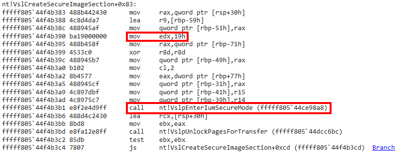
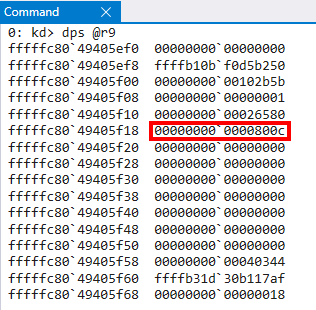
The Secure System Call Number, or SSCN, is stored in the RDX register. The R9 register, although not obvious from the screenshot above, is responsible for storing the packed Secure System Call arguments. These arguments are packed in the form of a in-memory typedef struct structure (which we will look at later).
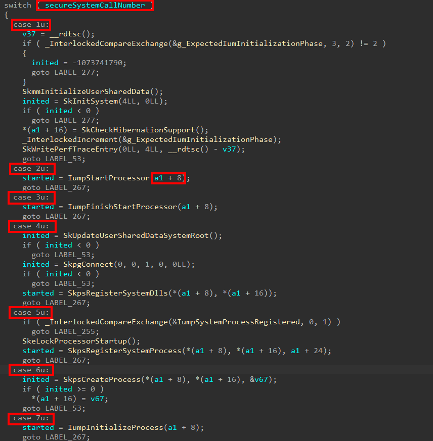
On the Secure Kernel side, the function securekernel!IumInvokeSecureService is a very large function which is the “entry point” for Secure System Calls. This contains a large switch/case statement that correlates a given SSCN to a specific dispatch function handler. The exact same order these arguments are packed is the exact same order they will be unpacked and operated on by the Secure Kernel (in the screenshot below, a1 is the address of the structure, and we can see how various offsets are being extracted from the structure, which is due to struct->Member access).
Now that we have a bit of an understanding here, let’s move on to see how the Secure System Call mechanism is used to help Secure Kernel create a Secure Image object!
SECURE_IMAGE (Non-Comprehensive!) Creation Overview
Although by no means is this a surefire way to identify this data, a method that could be employed to locate the functionality for creating Secure Image objects is to just search for terms like SecureImage in the Secure Kernel symbols. Within the call to securekernel!SkmmCreateSecureImageSection we see a call to an externally-imported function, skci!SkciCreateSecureImage.
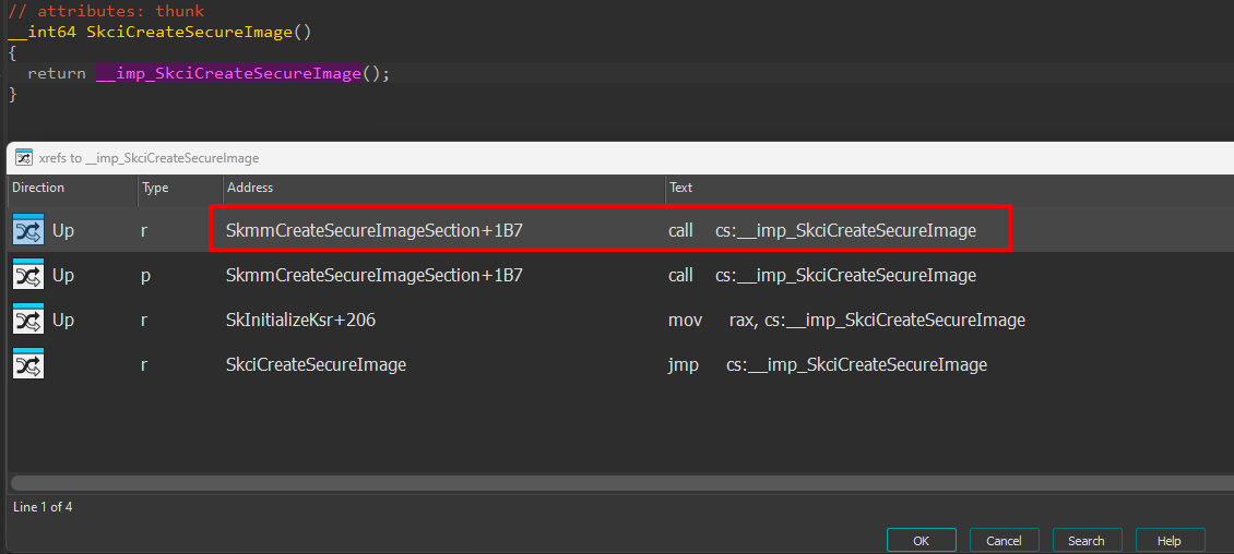
This means it is highly likely that securekernel!SkmmCreateSecureImageSection is responsible for accepting some parameters surrounding the Secure Image object creation and forwarding that on to skci!SkciCreateSecureImage. Focusing our attention on securekernel!SkmmCreateSecureImageSection we can see that this functionality (securekernel!SkmmCreateSecureImageSection) is triggered through a Secure System Call with an SSCN of 0x19 (the screenshot below is from the securekernel!IumInvokeSecureService Secure System Call dispatch function).
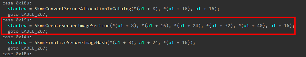
Again, by no means is this correct in all cases, but I have noticed that most of the time when a Secure System Call is issued from ntoskrnl.exe, the corresponding “lowest-level function”, which is responsible for invoking nt!VslpEnterIumSecureMode, has a similar name to the associated sispatch function in securekernel.exe which handles the Secure System Call. Luckily this applies here and the function which issues the SSCN of 0x19 is the nt!VslCreateSecureImageSection function.
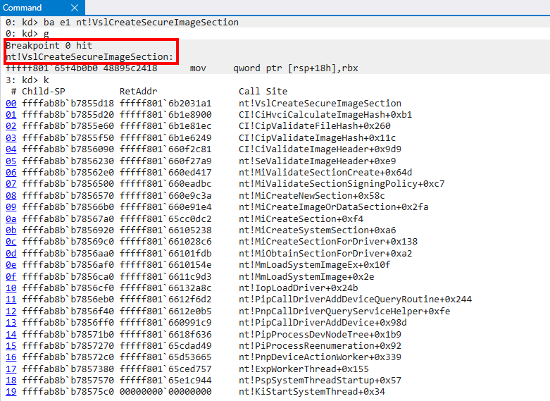
Based on the call stack here, we can see that when a new section object is created for a target driver image being loaded, the ci.dll module is dispatched in order to determine if the image is compatible with HVCI (if it isn’t, STATUS_INVALID_IMAGE_HASH is returned). Examining the parameters of the Secure System Call reveals the following.
Note that at several points I will have restarted the machine the analysis was performed on and due to KASLR the addresses will change. I will provide enough context in the post to overcome this obstacle.
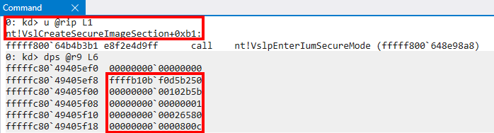
With Secure System Calls, the first parameter (seems to be) always 0 and/or reserved. This means the arguments to create a Secure Image object are packed as follows.
typedef struct _SECURE_IMAGE_CREATE_ARGS
{
    PVOID Reserved;
    PVOID VirtualAddress;
    PVOID PageFrameNumber;
    bool Unknown;
    ULONG Unknown;
    ULONG Unknown1;
} SECURE_IMAGE_CREATE_ARGS;
As a small point of contention, I know that the page frame number is such because I am used to dealing with looking into memory operations that involve both physical and virtual addresses. Anytime I see I am dealing with some sort of lower-level concept, like loading a driver into memory and I see a value that looks like a ULONG paired with a virtual address, I always assume this could be a PFN. I always assume this further in cases especially when the ULONG value is not aligned. A physical memory address is simply (page frame number *
0x1000), plus any potential offset. Since there is not0or00at the end of the address, this tells me that this is the page frame number. This is not a “sure” method to do this, but I will show how I validated this below.
At first, I was pretty stuck on what this first virtual address was used for. We previously saw the call stack which is responsible for invoking nt!VslCreateSecureImageSection. If you trace execution in IDA, however, you will quickly see this call stack is a bit convoluted as most of the functions called are called via function pointer as an input parameter from other functions making tracing the arguments a bit difficult. Fortunately, I saw that this virtual address was used in a call to securekernel!SkmmMapDataTransfer almost immediately within the Secure System Call handler function (securekernel!SkmmCreateSecureImageSection). Note although IDA is annotated a bit with additional information, we will get to that shortly.

It seems this function is actually publicly-documented thanks to Saar Amar and Daniel King’s BlackHat talk! This actually reveals to us that the first argument is an MDL (Memory Descriptor List) while the second parameter, which is PageFrameNumber, is a page frame number which we don’t know its use yet.
According to the talk, securekernel.exe tends to use MDLs, which are provided by VTL 0, for cases where data may need to be accessed by VTL 1. By no means is this an MDL internals post, but I will give a brief overview quickly. An MDL (nt!_MDL) is effectively a fixed-sized header which is prepended to a variable-length array of page frame numbers (PFNs). Virtual memory, as we know, is contiguous. The normal size of a page on Windows is 4096, or 0x1000 bytes. Using a contrived example (not taking into account any optimizations/etc.), let’s say a piece of malware allocated 0x2000 bytes of memory and stored shellcode in that same allocation. We could expect the layout of memory to look as follows.
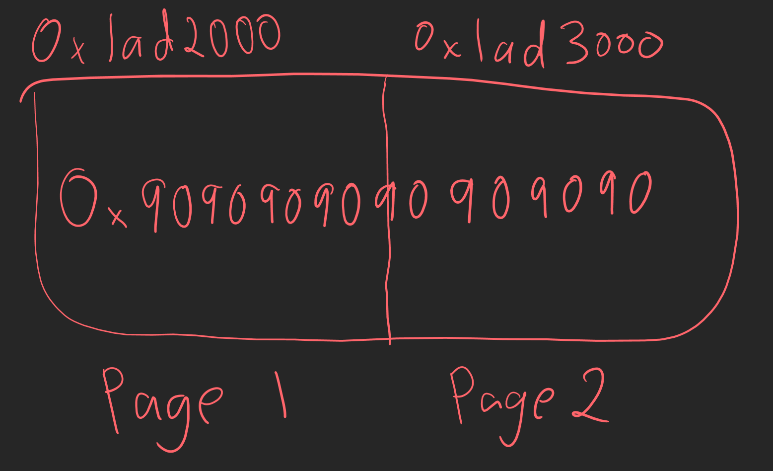
We can see in this example the shellcode spans the virtual pages 0x1ad2000 and 0x1ad3000. However, this is the virtual location, which is contiguous. In the next example, the reality of the situation creeps in as the physical pages which back the shellcode are in two separate locations.
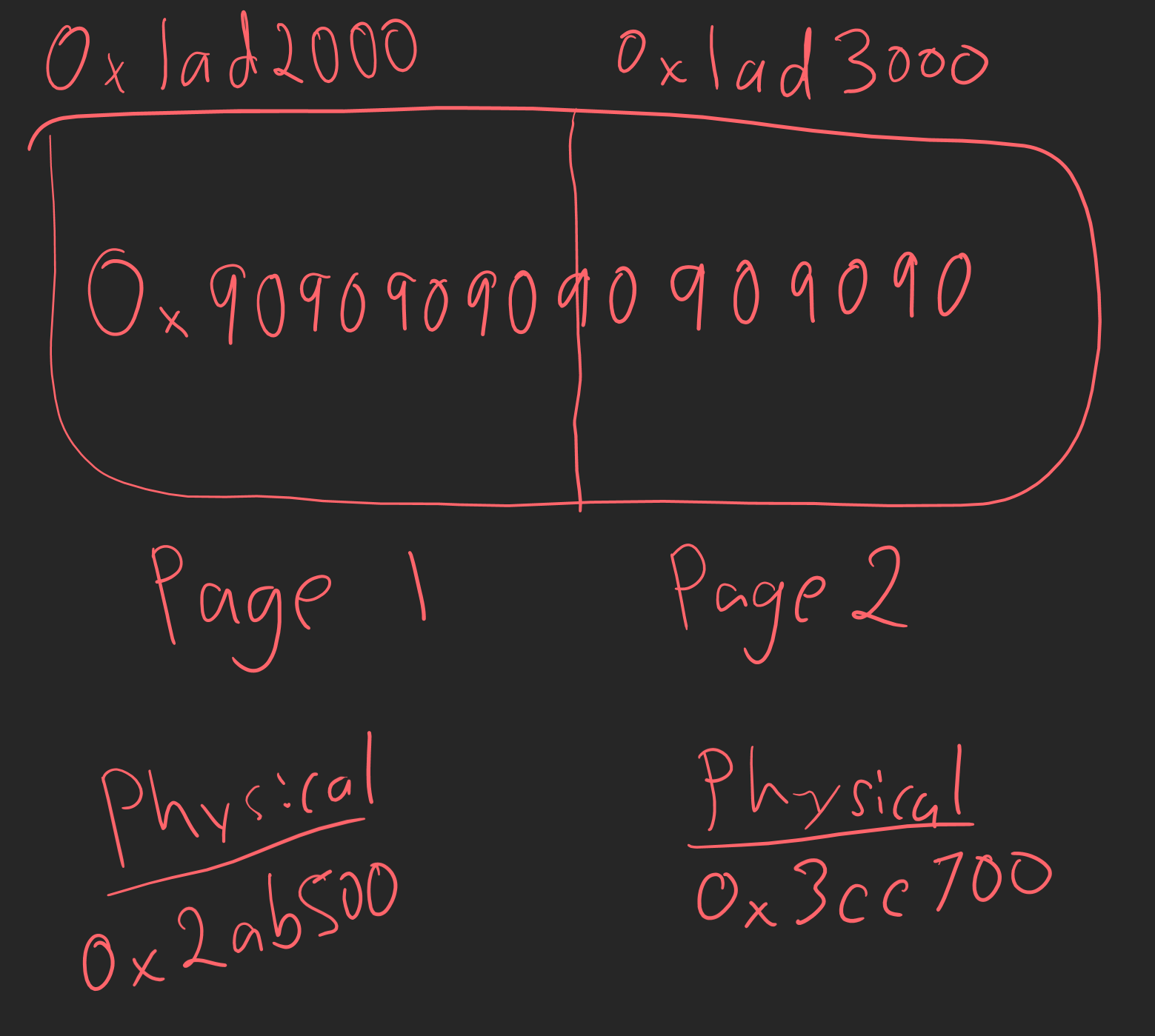
An MDL would be used in this case to describe the physical layout of the memory of a virtual memory region. The MDL is used to say “hey I have this contiguous buffer in virtual memory, but here are the physical non-contiguous page(s) which describe this contiguous range of virtual memory”.
MDLs are also typically used for direct memory access (DMA) operations. DMA operations don’t have the luxury of much verification, because they need to access data quickly (think UDP vs TCP). Because of this an MDL is used because it typically first locks the memory range described into memory so that the DMA operation doesn’t ever access invalid memory.
One of the main features of an MDL is that it allows multiple mappings for the given virtual address a given MDL described (the StartVa is the beginning of the virtual address range the MDL describes). For instance, consider an MDL with the following layout: a user-mode buffer is described by an MDL’s StartVa. As we know, user-mode addresses are only valid within the process context of which they reside (and the address space is per-process based on the current page table directory loaded into the CR3 register). Let’s say that a driver, which is in an arbitrary context needs to access the information in the user-mode buffer contained in Mdl->StartVa. If the driver goes to access this, and the process context is processA.exe but the address was only valid in processB.exe, you are accessing invalid memory and you would cause a crash.
An MDL allows you, through the MmGetSystemAddressForMdlSafe API, to actually request that the system map this memory into the system address space, from the non-paged pool. This allows us to access the contents of the user-mode buffer, through a kernel-mode address, in an arbitrary process context.
Now, using that knowledge, we can see that the exact same reason VTL 0 and VTL 1 use MDLs! We can think of VTL 0 as the “user-mode” portion, and VTL 1 as the “kernel-mode” portion, where VTL 0 has an address with data that VTL 1 wants. VTL 1 can take that data (in the form of an MDL) and map it into VTL 1 so it can safely access the contents of memory described by the MDL.
Taking a look back at how the MDL looks, we can see that StartVa, which is the buffer the MDL describes, is some sort of base address. We can confirm this is actually the base address of an image being loaded because it contains nt!_IMAGE_DOS_HEADER header (0x5a4d is the magic (MZ) for a PE file and can be found in the beginning of the image, which is what a kernel image is).
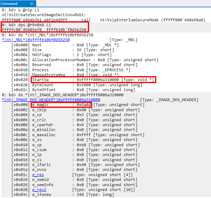
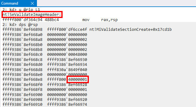
However, although this looks to be the “base image”, based on the alignment of Mdl->StartVa, we can see quickly that ByteCount tells us only the first 0x1000 bytes of this memory allocation are accessible via this MDL. The ByteCount of an MDL denotes the size of the range being described by the MDL. Usually the first 0x1000 bytes of an image are reserved for all of the headers (IMAGE_DOS_HEADER, IMAGE_FILE_HEADER, etc.). If we recall the original call stack (provided below for completeness) we can actually see that the NT function nt!SeValidateImageHeader is responsible for redirecting execution to ci.dll (which eventually results in the Secure System Call). This means in reality, although the StartVa is aligned to look like a base address, we are really just dealing with the headers of the target image at this point. Even though the StartVa is aligned like a base address, the fact of the matter is the actual address is not relevant to us - only the headers are.
As a point of contention before we move on, we can do basic retroactive analysis based on the call stack to clearly see that the image has only been mapped into memory. It has not been fully loaded - and only the initial section object that backs the image is present in virtual memory. As we do more analysis in this post, we will also verify this to be the case with actual data that shows many of the default values in the headers, from disk, haven’t been fixed up (which normally happens when the image is fully loaded).
Great! Now that we know this first paramter is an MDL that contains the image headers, the next thing that needs to happen is for securekernel.exe to figure out how to safely access the contents region described by the MDL (which are the headers).
The first thing that VTL 1 will do is take the MDL we just showed, provided by VTL 0, and creates a new MDL in VTL 1 that describes the provided MDL from VTL 0. In other words, the new MDL will be laid out as follows.
Vtl1CopyOfVtl0Mdl->StartVa = page_aligned_address_mdl_starts_in;
Vtl1CopyOfVtl0Mdl->ByteOffset = offset_from_page_aligned_address_to_actual_address;
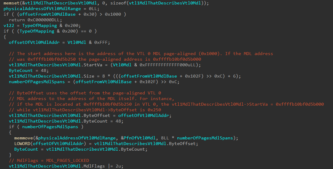
MDLs usually work with a page-aligned address as the base, and any offset in ByteOffset. This is why the VTL 0 MDL is address is first page-aligned (Vtl0Mdl & 0xFFFFFFFFFFFFF000), and the offset to the MDL in the page is set in ByteOffset.
Additionally, from the previous image, we can now realize what the first page frame number used in our Secure System Call parameters is used for. This is the PFN which corresponds to the MDL (the parameter PfnOfVtl0Mdl). We can validate this in WinDbg.
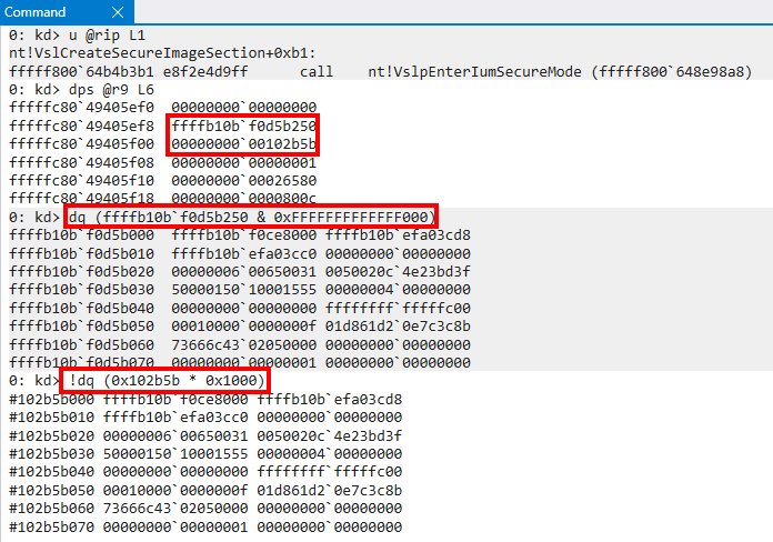
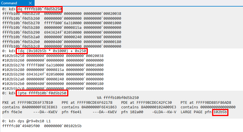
We know that a physical page of memory is simply (page frame number * PAGE_SIZE + any offset). Although we can see in the previous screenshot that the contents of memory for the page-aligned address of the MDL and the physical memory correspond, if we add the page offset (0x250 in this case) we can clearly see that there is no doubt this is the PFN for the VTL 0 MDL. We can additionally see that for the PTE of the VTL0 MDL the PFNs align!
This MDL, after construction, has StartVa mapped into VTL 1. At this point, for all intents and purposes, vtl1MdlThatDescribesVtl0Mdl->MappedSystemVa contains the VTL 1 mapping of the VTL 0 MDL! All integrity checks are then performed on the MDL.
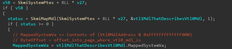
VTL 1 has now mapped the VTL 0 MDL (using another MDL). MappedSystemVa is now a pointer to the VTL 1 mapping of the VTL 0 MDL, and the integrity checks now occur on this new mapping, instead of directly operating on the VTL 0 MDL. After confirming the VTL 0 MDL contains legitimate data (the large if statement in the screenshot below), another MDL (not the MDL from VTL 0, not the MDL created by VTL 1 to describe the MDL from VTL 0, but a third, new MDL) is created. This MDL will be an actual copy of the now verified contents of the VTL 0 MDL. In otherwords, thirdNewMDl->StartVa = StartAddressOfHeaders (which is start of the image we are dealing with in the first place to create a securekernel!_SECURE_IMAGE structure).
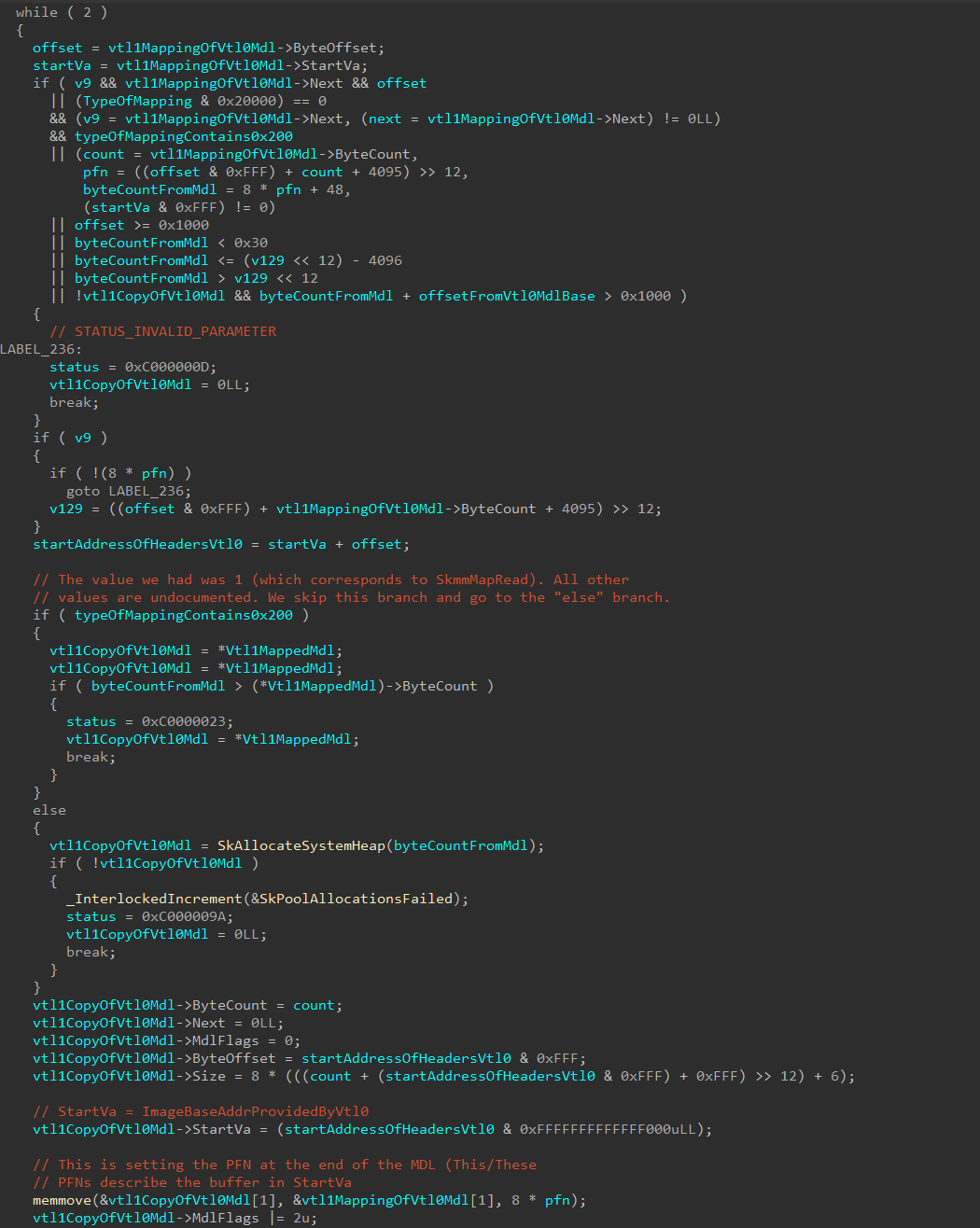
We can now clearly see that since VTL 1 has created this new MDL, the page frame number (PFN) of the VTL 0 MDL was provided since a mapping of virtual memory is simply just creating another virtual page which is backed by a common physical page. When the new MDL is mapped, the Secure Kernel can then use NewMdl->MappedSystemVa to safely access, in the Secure Kernel virtual address space, the header information provided by the MDL from VTL 0.
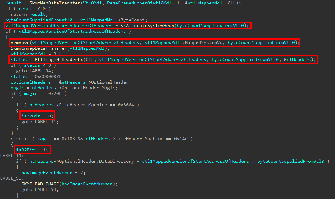
The VTL 1 MDL, which is mapped into VTL 1 and has now had all contents verified. We now return back to the original caller where we started in the first place - securekernel!SkmmCreateSecureImageSection. This then allows VTL 1 to have a memory buffer where the contents of the image from VTL 0 resides. We can clearly see below this is immediately used in a call to RtlImageNtHeaderEx in order to validate that the memory which VTL 0 sent in the first place contains a legitimate image in order to create a securekernel!_SECURE_IMAGE object. It is also at this point that we determine if we are dealing with the 32-bit or 64-bit architecture.
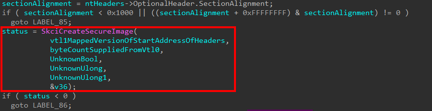
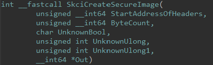
More information is then gathered, such as the size of the optional headers, the section alignment, etc. Once this information is flushed out, a call to an external function SkciCreateSecureImage is made. Based on the naming convention, we can infer this function resides in skci.dll.
We know in the original Secure System Call that the second parameter is the PFN which backs the VTL 0 MDL. UnknownUlong and UnknownUlong1 here are the 4th and 5th parameters, respectively, passed to securekernel!SkmmCreateSecureImageSection. As of right now we also don’t know what they are. The last value I noticed was consistently this 0x800c constant across multiple calls to securekernel!SkmmCreateSecureImageSection.
Opening skci.dll in IDA, we can examine this function further, which seemingly is responsible for creating the secure image.
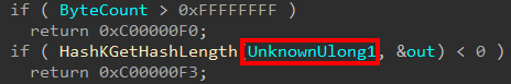
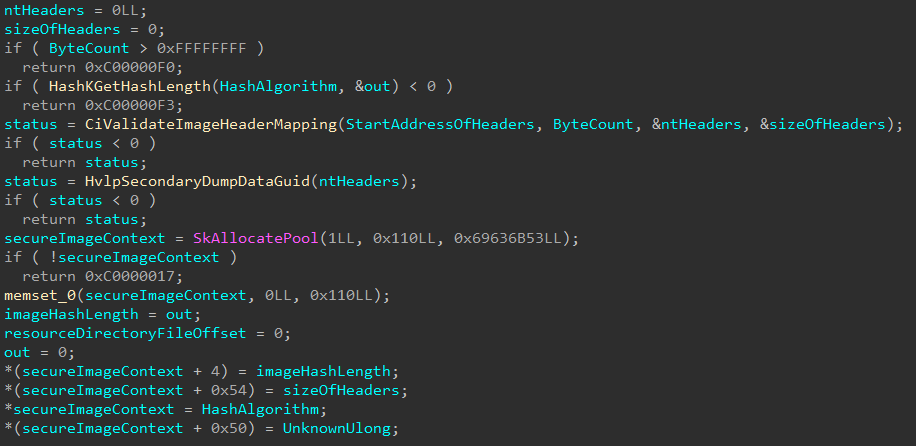
Taking a look into this function a bit more, we can see this function doesn’t create the object itself but it creates a “Secure Image Context”, which on this build of Windows is 0x110 bytes in size. The first function called in skci!SkciCreateSecureImage is skci!HashKGetHashLength. This is a very simple function, and it accepts two parameters - one an input and one an output or return. The input parameter is our last Secure System Call parameter, which was 0x800C.
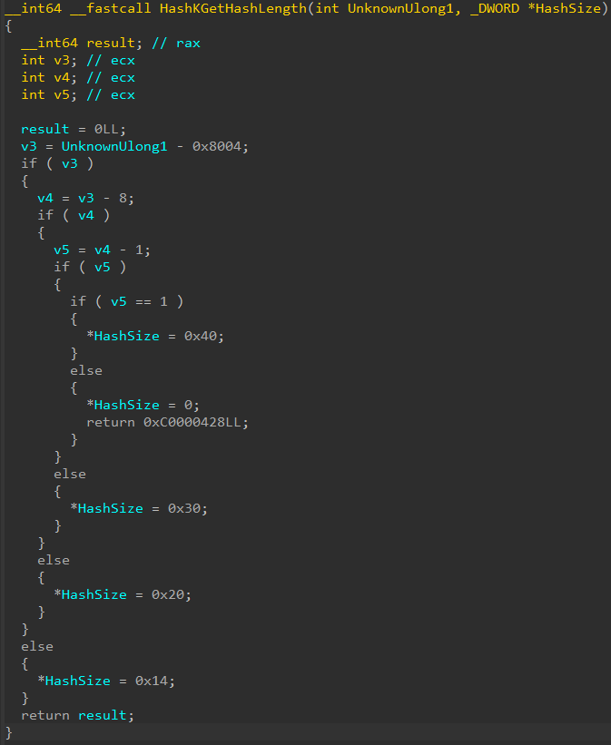
Although IDA’s decompilation here is a bit confusing, what this function does is look for a few constant values - one of the options is 0x800C. If the value 0x800C is provided, the output parameter (which is the hash size based on function name and the fact the actual return value is of type NTSTATUS) is set to 0x20. This effectively insinuates that since obviously 0x800C is not a 0x20 byte value, nor a hash, that 0x800C must instead refer to a type of hash which is likely associated with an image. We can then essentially say that the last Secure System Call parameter for secure image creation is the “type” of hash associated with this image. In fact, looking at cross references to this function reveals that the function skci!CiInitializeCatalogs passes the parameter skci!g_CiMinimumHashAlgorithm as the first parameter to this function - meaning that the first parameter actually specifies the hash algorithm.
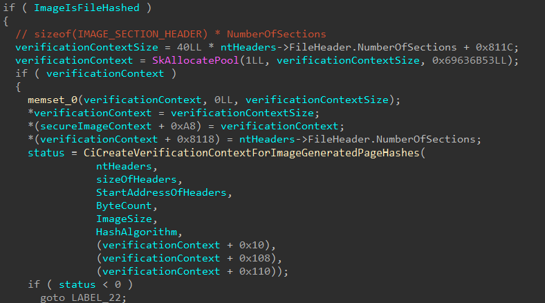
After calculating the hash size, the Secure Image Context is then built out. This starts by obtaining the Image Headers (nt!_IMAGE_NT_HEADERS64) headers for the image. Then the Secure Image Context is allocated from the pool and initialized to 0 (this is how we know the Secure Image Context is 0x110 bytes in size). The various sections contained in the image are used to build out much of the information tracked by the Secure Image Context.
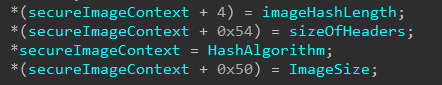
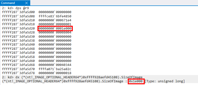
Note that
UnknownULong1was updated toImageSize. I wish I had a better way to explain as to how I identified this, but in reality it happenstance as I was examining the optional headers I realized I had seen this value before. See the image below to validate that the value from the Secure System Call arguments corresponds toSizeOfImage.
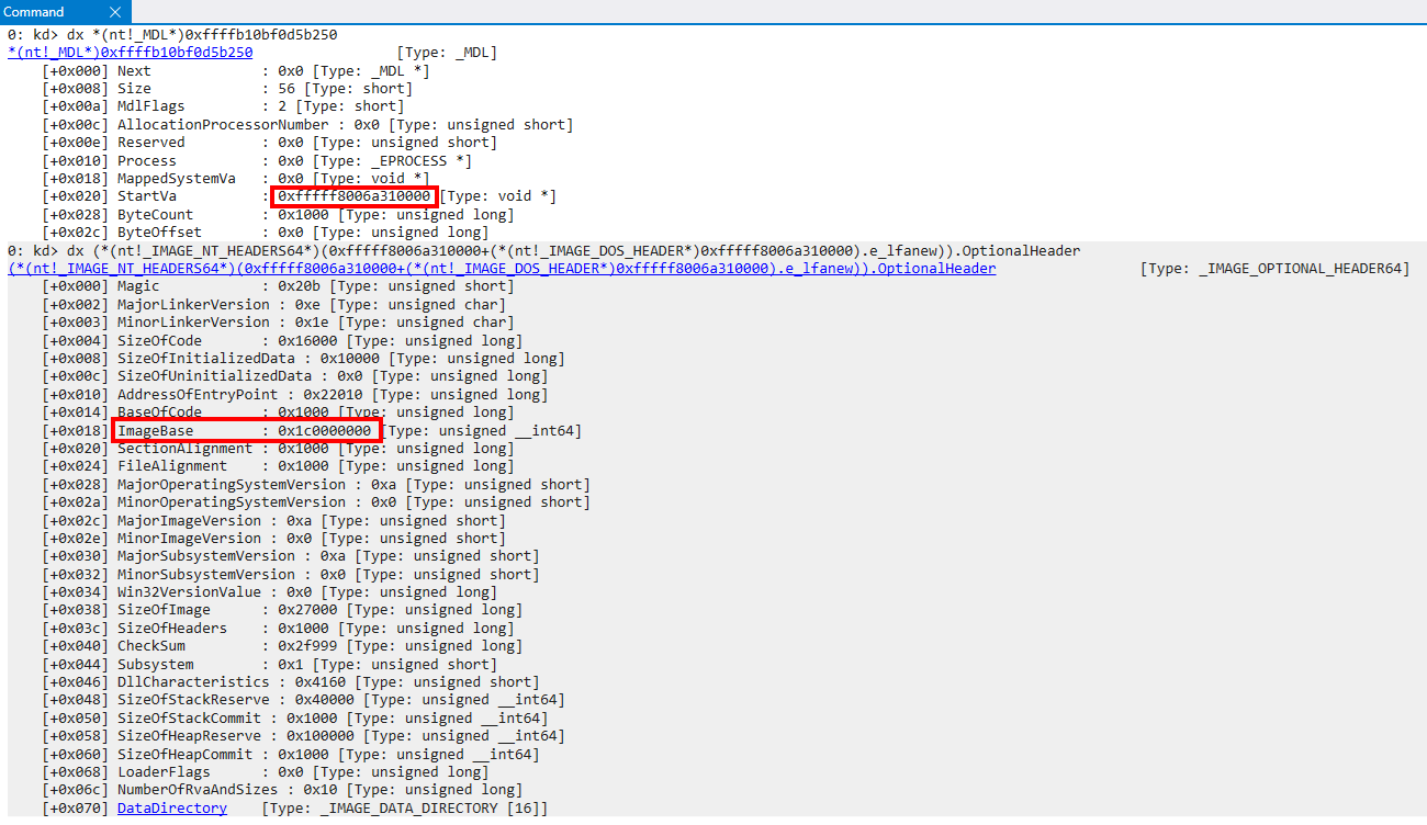
One thing to keep in mind here is a SECURE_IMAGE object is created before ntoskrnl.exe has had a chance actually perform the full loading of the image. At this point the image is mapped into virtual memory, but not loaded. We can see this by examining the nt!_IMAGE_NT_HEADERS64 structure and seeing that ImageBase in the nt!_IMAGE_OPTIONAL_HEADER64 structure is still set to a generic 0x1c0000000 address instead of the virtual address which the image is currently mapped (because this information has not yet been updated as part of the loading process).
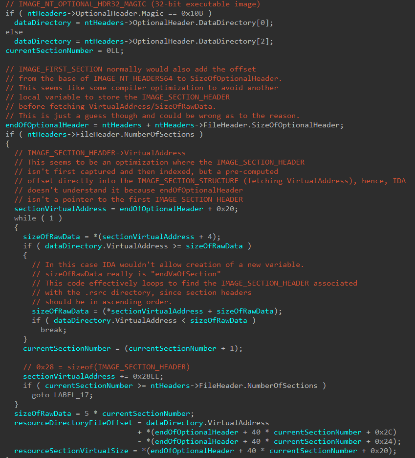
Next in the Secure Image Context creation functionality, the Secure Kernel locates the .rsrc section of the image and the Resource Data Directory. This information is used to calculate the file offset to the Resource Data Directory and also captures the virtual size of the .rsrc section.

After this skci!SkciCreateSecureImage will, if the parameter we previously identified as UnknownBool is set to true, allocate some pool memory which will be used in a call to skci!CiCreateVerificationContextForImageGeneratedPageHashes. This infers to us the “unknown bool” is really an indicator whether or not to create the Verification Context. A context, in this instance, refers to some memory (usually in the form of a structure) which contains information related to the context in which something was created, but wouldn’t be available later otherwise.
The reader should know - I asked Andrea a question about this. The answer here is that a file can either be page-hashed or file-hashed signed. Although the bool gates creating the Verification Context, it is more aptly used to describe if a file is file-hashed or page-hashed. If the image is file-hashed signed, the Verification Context is created. For page-hashed files there is no need for the additional context information (we will see why shortly).
This begs the question - how do we know if we are dealing with a file that was page-hashed signed or file-hash signed? Taking a short detour, this starts in the initial section object creation (nt!MiCreateNewSection). During this time a bitmask, based on the parameters surrounding the creation of the section object that will back the loaded driver is formed. A partially-reversed CREATE_SECTION_PACKET structure from my friend Johnny Shaw outlines this. Packet->Flags is one of the main factors that dictates how this new bitmask is formulated. In the case of the analysis being done in this blog post, when bit 21 (PacketFlags & 0x100000) and when bit 6 (PacketFlags & 0x20) are set, we get the value for our new mask - which has a value of 0x40000001. This bitmask is then carried through to the header validation functions, as seen below.
This bitmask will finally make its way to ci!CiGetActionsForImage. This call, as the name infers, returns another bitmask based on our 0x40000001 bitmask. The caller of ci!CiGetActionsForImage is ci!CiValidateImageHeader. This new returned bitmask gives instructions to the header validation function as to what actions to take for validation.

As previous art shows, depending on the bitmask returned the header validation is going to be done via page hash validation, or file hash validation by supplying a function pointer to the actual validation function.
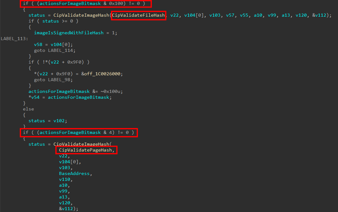
The two terms (page-hash signed and file-hash signed) can be very confusing - and there is very little information about them in the wild. A file-hashed file is one that has the entire contents of the file itself hashed. However, we must consider things like a driver being paged out and paged in. When an image is paged in, for instance, it needs to be validated. Images in this case are always verified using page hashes, and never file hashes (I want to make clear I only know the following information because I asked Andrea). Because a file-hashed file would not have page hash information available (obviously since it is “file-hashed”), skci.dll will create something called a “Page Hash Context” (which we will see shortly) for file-hashed images so that they are compatible with the requirement to verify information using page hashes.
As a point of contention, this means we have determined the arguments used for a Secure Image Secure System Call.
typedef struct _SECURE_IMAGE_CREATE_ARGS
{
    PVOID Reserved;
    PVOID Vtl0MdlImageHeaders;
    PVOID PageFrameNumberForMdl;
    bool ImageeIsFileHashedCreateVerificationContext;
    ULONG ImageSize;
    ULONG HashAlgorithm;
} SECURE_IMAGE_CREATE_ARGS;
Moving on, the first thing this function (since we are dealing with a file-hashed image) does is actually call two functions which are responsible for creating additional contexts - the first is an “Image Hash Context” and the second is a “Page Hash Context”. These contexts are stored in the main Verification Context.
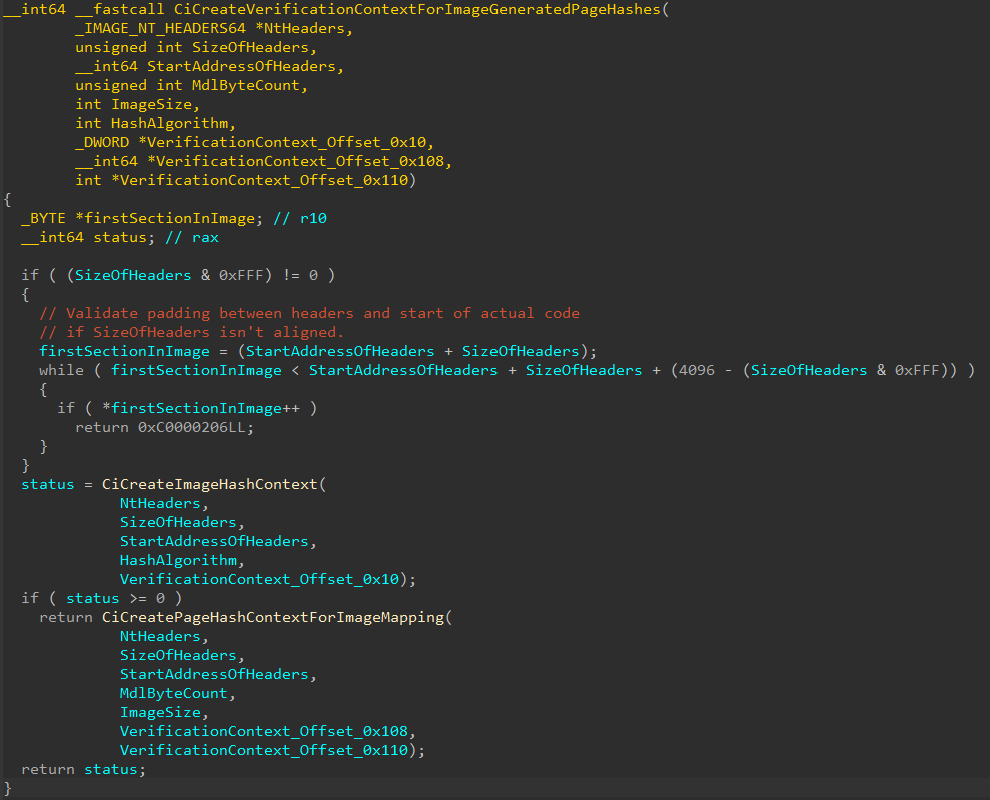
skci!CiCreateImageHashContext is a relatively small wrapper that simply takes the hashing algorithm passed in as part of the Secure Image Secure System Call (0x800C in our case) and uses this in a call to skci!SymCryptSha256Init. skci!SymCryptSha256Init takes the hash algorithm (0x800C) and uses it to create the Image Hash Context for our image (which really isn’t so much a “context” as it mainly just contains the size of the hash and the hashing data itself).
The Page Hash Context information is only produced for a file-hashed image. Otherwise file-hashed images would not have a way to be verified in the future as only page hashes are used for verification of the image. Page Hash Context are slightly more involved, but provide much of the same information. skci!CiCreatePageHashContextForImageMapping is responsible for creating this context and VerificationContext_Offset_0x108 stores the actual Page Hash Context.
The Page Hash Context logic begins by using SizeOfRawData from each of the section headers (IMAGE_SECTION_HEADER) to iterate over of the sections available in the image being processed and to capture how many pages make up each section (determines how many pages make up all of the sections of the image).
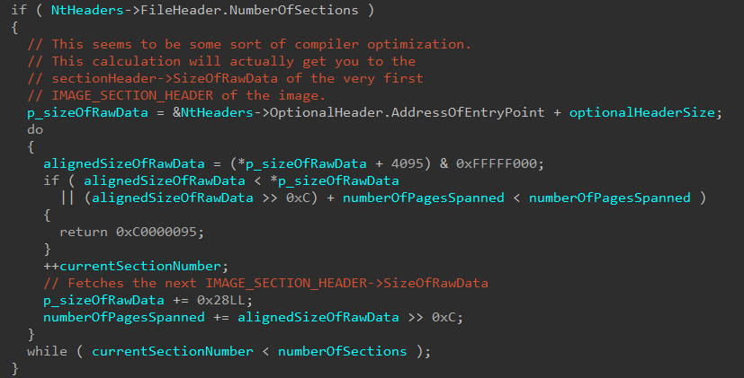
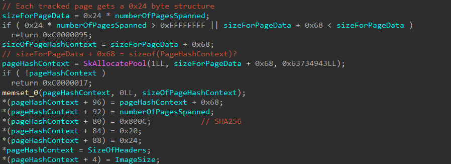
This information, along with IMAGE_OPTIONAL_HEADER->SizeOfHeaders, the size of the image itself, and the number of pages that span the sections of the image are stored in the Page Hash Context. Additionally, the Page Hash Context is then allocated based on the size of the sections (to ensure enough room is present to store all of the needed information).
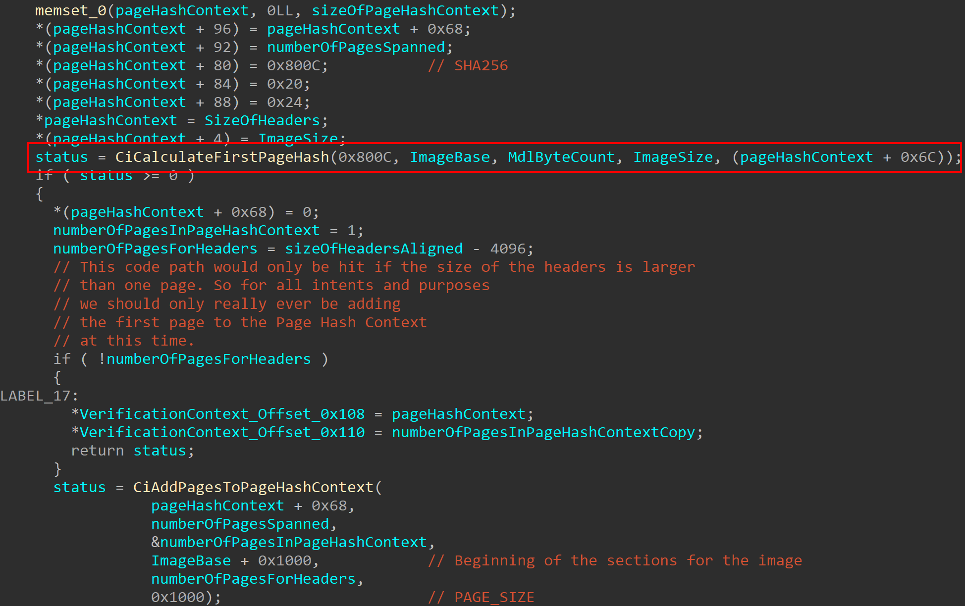
After this, the Page Hash Context information is filled out. This begins by only storing the first page of the image in the Page Hash Context. The rest of the pages in each of the sections of the target image are filled out via skci!SkciValidateImageData, which is triggered by a separate Secure System Call. This comes at a later stage after the current Secure System Call has returned but before we have left the original nt!MiCreateNewSection function. We will see this in a future blog post.
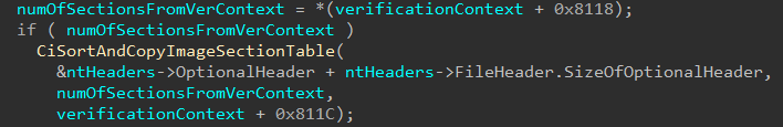
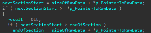
Now that the initial Verification Context (which contains also the Page Hash and Image Hash Contexts) have been created (but as we know will be updated with more information later), skci!SkciCreateSecureImage will then sort and copy information from the Image Section Headers and store them in the Verification Context. This function will also calculate the file offset for the last section in the image by computing PointerToRawData + SizeOfRawData in the skci!CiGetFileOffsetAfterLastRawSectionData function.
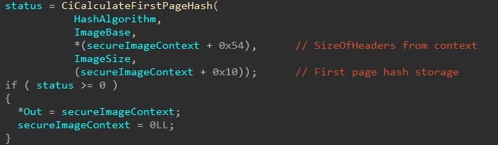
After this, the Secure Image Context creation work is almost done. The last thing this function does is compute the hash of the first page of the image and stores it in the Secure Image Context directly this time. This also means the Secure Image Context is returned by the caller of skci!SkciCreateSecureImage, which is the Secure Kernel function servicing the original Secure System Call.
Note that previously we saw
skci!CiAddPagesToPageHashContextcalled withinskci!CiCreatePageHashContextForImageMapping. In the call in the above image, the fourth parameter isSizeOfHeaders, but in the call withinskci!CiCreatePageHashContextForImageMappingthe parameter wasMdlByteCount- which is theByteCountprovided earlier by the MDL in the Secure System Call arguments. In our case,SizeOfHeadersand theByteCountare both0x1000- which infers that when the MDL is constructured, theByteCountis set to0x1000based on theSizeOfHeadersfrom the Optional Header. This validates what we mentioned at the beginning of the blog where although the “base address” is used as the first Secure System Call parameter, this could be more specifically referred to as the “headers” for the image.
The Secure Kernel maintains a table of all active Secure Images that are known. There are two very similar tables, which are used to track threads and NARs (securekernel!SkiThreadTable/securekernel!SkiNarTable). These are of type “sparse tables”. A sparse table is a computer science concept that effectively works like a static array of data, but instead of it being unordered the data is ordered which allows for faster lookups. It works by supporting 0x10000000, or 256,000 entries. Note that these entries are not all allocated at once, but are simply “reserved” in the sense that the entries that are not in use are not mapped.

Secure Images are tracked via the securekernel!SkmiImageTable symbol. This table, as a side note, is initialized when the Secure Kernel initializes. The Secure Pool, the Secure Image infrastructure, and the Code Integrity infrastructure are initialized after the kernel-mode user-shared data page is mapped into the Secure Kernel.
The Secure Kernel first allocates an entry in the table where this Secure Image object will be stored. To calculate the index where the object will be stored, securekernel!SkmmAllocateSparseTableEntry is called. This creates a sizeof(ULONG_PTR) “index” structure. This determines the index into the table where the object is stored. In the case of storing a new entry, on 64-bit, the first 4 bytes provide the index and the last 4 bytes are unused (or, if they are used, I couldn’t see where). This is all done back in the original function securekernel!SkmmCreateSecureImageSection, after the function which creates the Secure Image Context has returned.
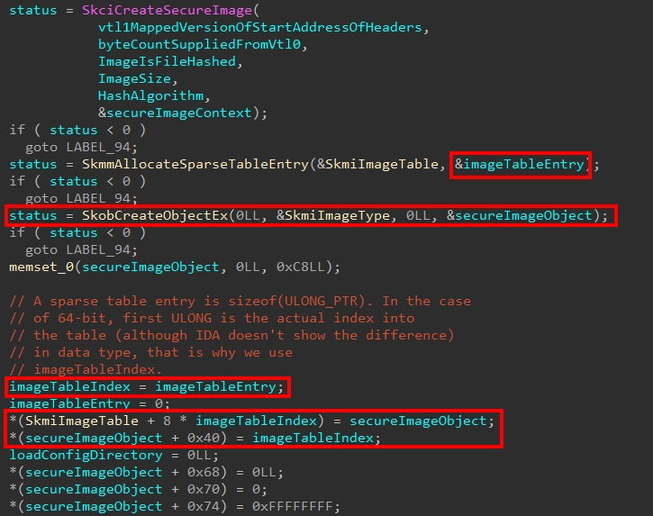
As we can also see above, this is where our actual Secure Image object is created. As the functionality of securekernel!SkmmCreateSecureImageSection continues, this object will get filled out with more and more information. Some of the first data collected is if the image is already loaded in a valid kernel address. From the blog earlier, we mentioned the Secure Image loading occurs when an image is first mapped but not loaded. This seems to infer it is possible for a Secure Image to be at least already loaded at a valid kernel-mode address. If it is loaded, a bitwise OR happens with a mask of 0x1000 to indicate this. The entry point of the image is captured, and the previously-allocated Secure Image Context data is saved. Also among the first information collected is the Virtual Address and Size of the Load Config Data Directory.
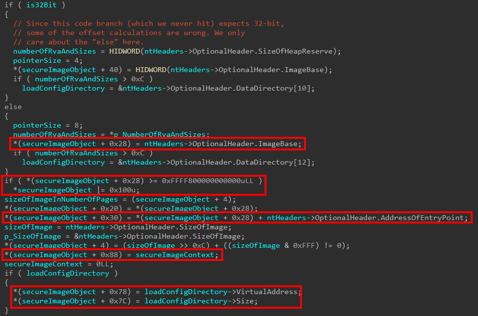
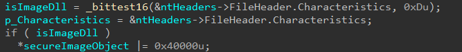
The next items start by determining if the image being loaded is characterized as a DLL (this is technically possible, for example, ci.dll is loaded into kernel-mode) by checking if the 13th bit is set in the FileHeader.Characteristics bitmask.
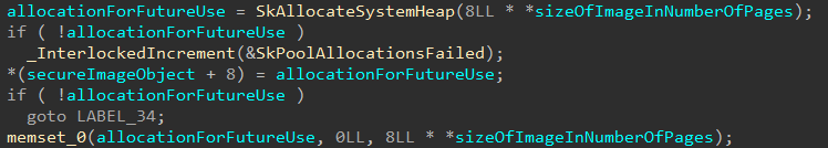
After this, the Secure Image creation logic will create an allocation based on the size of the image from NtHeaders->OptionalHeader->SizeOfImage. This allocation is not touched again during the initialization logic.
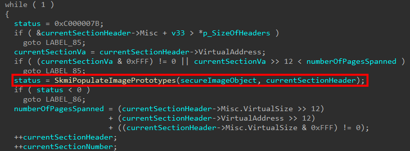
At this point, for each of the sections in the image, the prototype PTEs for the image (via securekernel!SkmiPopulateImagePrototypes) are populated. If you are not familiar, when a shared memory region is shared for, as an example, between two-processes an issue arises at the PTE level. A prototype PTE allows easily for the memory manager to track pages that are shared between two processes. As even Windows Internals, 7th Edition, Part 1, Chapter 5 states - prototype PTEs are created for a pagefile-backed section object when it is first created. The same this effectively is happening here, but instead of actually creating the prototype PTEs (because this is done in VTL 0), the Secure Kernel now obtains a pointer to the prototype PTEs.
After this, additional section data and relocation information for the image is captured. This first starts by checking if the relocation information is stripped and, if the information hasn’t been stripped, the code captures the Image Data Directory associated with relocation information.
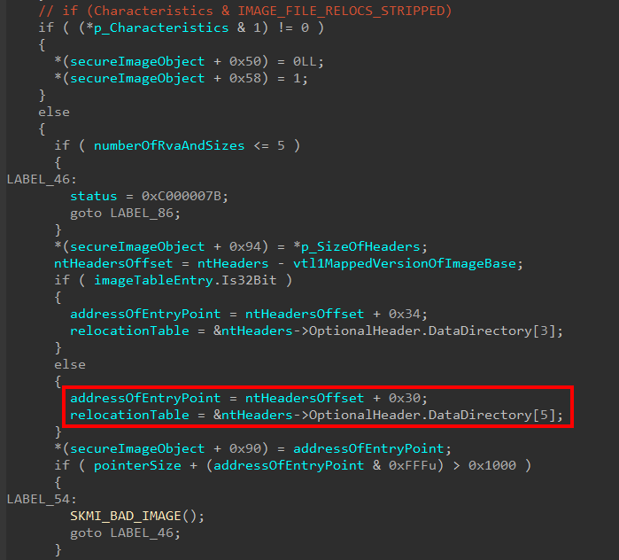
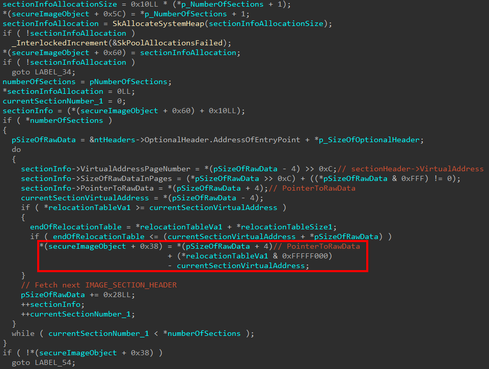
The next thing that occurs is, again, each of the present sections is iterated over. This is done to capture some important information about each section in a memory allocation that is stored in the Secure Image object. Specifically here, relocation information is being processed. The Secure Image object creation logic will first allocate some memory in order to store the Virtual Address page number, size of the raw data in number of pages, and pointer to raw data for the section header that is currently being processed. As a part of each check, the logic determines if the relocation table falls within the range of the current section. If it does, the file offset to the relocation table is calculated and stored in the Secure Image object.
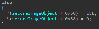
Additionally, we saw previously that if the relocation information was stripped out of the image, the Secure Image object (at offset 0x50 and 0x58) were updated with values of false and true, 0 and 1, respectively. This seems to indicate why the relocation information may not be present. In this case, however, if the relocation information wasn’t stripped but there legitimately was no relocation information available (the Image Data Directory entry for the relocation data was zero), these boolean values are updated to true and false, 1 and 0, respectively. This would seem to indicate to the Secure Image object why the relocation information may or may not be present.
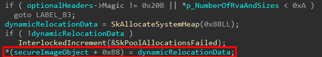
The last bits of information the Secure Image object creation logic processes are:
- Is the image being processed a 64-bit executable image or are the number of data directories at least 10 decimal in amount to support the data directory we want to capture? If not, skip step 2.
- If the above is true, allocate and fill out the “Dynamic Relocation Data”
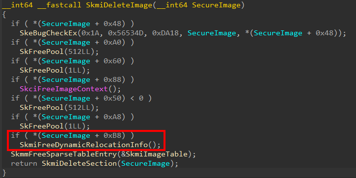
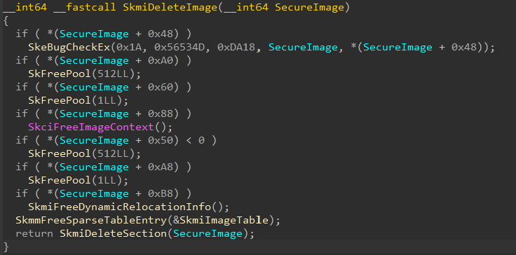
As a side-note, I only determines the proper name for this data is “Dynamic Relocation Data” because of the routine securekernel!SkmiDeleteImage - which is responsible for deleting a Secure Image object when the object’s reference count reaches 0 (after we get through this last bit of information that is processed, we will talk about this routine in more detail). In the securekernel!SkmiDeleteImage logic, a few pointers in the object itself are checked to see if they are allocated. If they are, they are freed (this makes sense, as we have seen there have been many more memory allocations than just the object itself). SecureImageObject + 0xB8 is checked as a place in the Secure Image object that is allocated. If the allocation is present, a function called securekernel!SkmiFreeDynamicRelocationInfo is called to presumably free this memory.
This would indicate that the “Dynamic Relocation Data” is being created in the Secure Image object creation logic.
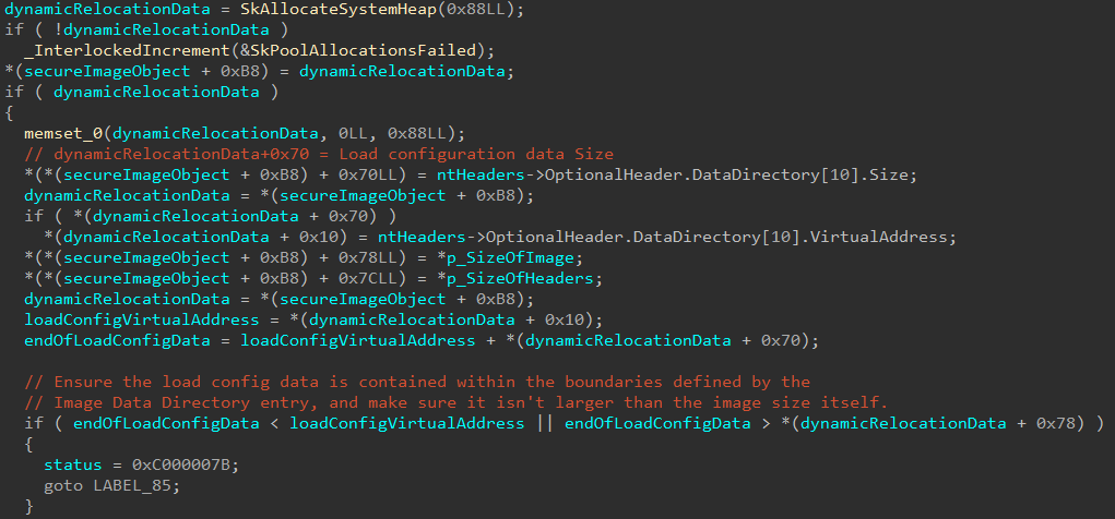
The information captured here refers to the load configuration Image Data Directory. The information about the load config data is verified, and the virtual address and size are captured and stored in the Secure Image object. This makes sense, as the dynamic relocation table is just the load config directory of an executable.
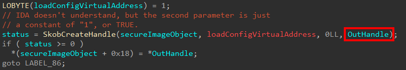
This is the last information the Secure Image object needs for the initialization (we know more information will be collected after this Secure System Call returns)! Up until this point, the last parameter we haven’t touched in the securekernel!SkmmCreateSecureImageSection function is the last parameter, which is actually an output parameter. The output parameter here is filled with the results of a call to securekernel!SkobCreateHandle.
If we look back at the initial Secure System Call dispatch function, this output parameter will be stored in the original Secure System Call arguments at offset 0x10 (16 decimal)
This handle is also stored in the Secure Image object itself. This also infers that when a Secure Image object is created, a handle to the object is returned to VTL 0/NT! This handle is eventually stored in the control area for the section object which backs the image (in VTL 0) itself. This is stored in ControlArea->u2.e2.SeImageStub.StrongImageReference.
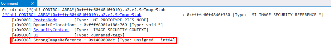
Note that this isn’t immediately stored in the Control Area of the section object. This happens later, as we will see in a subsequent blog post, but it is something at least to note here. As another point of contention, the way I knew this handle would eventually be stored here is because when I was previously doing analysis on NAR/NTE creation, which we will eventually talk about, this handle value was the first parameter passed as part of the Secure System Call.
This pretty much sums up the instantiation of the initial Secure Image object. The object is now created but not finalized - much more data still needs to be validated. Because this further validation happens after the Secure System Call returns, I will put that analysis into another blog post. The future post we will look at what ntoskrnl.exe, securekernel.exe, and skci.dll do with this object after the initial creation before the image is actually loaded fully into VTL 0. Before we close the blog post, it is worth taking a look the object itself and how it is treated by the Secure Kernel.
Secure Image Objects - Now What?
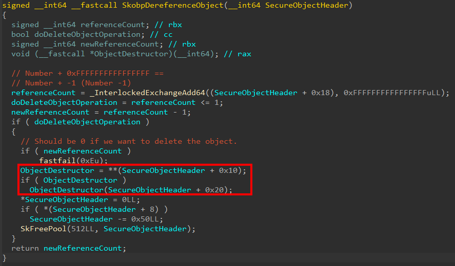
After the Secure Image object is created, the “clean-up” code for the end of the function (securekernel!SkmmCreateSecureSection) dereferences the object if the object was created but failure occured during the setting up of the initial object. Notice that the object is dereferenced at 0x20 bytes before the actual object address.

What does this mean? Objects are prepended with a header that contains metadata about the object itself. The reference count for an object, historically, on Windows is contained in the object header (for the normal kernel this is nt!_OBJECT_HEADER). This tells us that each object managed by the Secure Kernel has a 0x20 byte header! Taking a look at securekernel!SkobpDereferenceObject we can clearly see that within this header the reference count itself is stored at offset 0x18. We can also see that there is an object destructor, contained in the header itself.
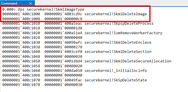
Just like regular NT objects, there is a similar “OBJECT_TYPE” setup (nt!PsProcessType, nt!PsThreadType, etc.). Taking a look at the image below, securekernel!SkmiImageType is used when referring to Secure Image Objects.

Existing art denotes that this object type pointer (securekernel!SkmiImageType) contains the destructor and size of the object. This can be corroborated by the interested reader by opening securekernel.exe as data in WinDbg (windbgx -z C:\Windows\system32\securekernel.exe) and looking at the object type directly. This reveals that for the securekernel!SkmiImageType symbol there is an object destructor and, as we saw earlier with the value 0xc8, the size of this type of object.
The following are a list of most of the valid objects in the Secure Kernel I located (although it is unclear without further analysis what many of them are used for):
- Secure Image Objects (
securekernel!SkmiImageType) - Secure HAL DMA Enabler Objects (
securekernel!SkhalpDmaEnablerType) - Secure HAL DMA Mapping Objects (
securekernel!SkhalpDmaMappingType) - Secure Enclave Objects (
securekernel!SkmiEnclaveType) - Secure Hal Extension Object (
securekernel!SkhalExtensionType) - Secure Allocation Object (
securekernel!SkmiSecureAllocationType) - Secure Thread Object (
securekernel!SkeThreadType) - Secure Shadow Synchronization Objects (events/semaphores) (
securekernel!SkeShadowSyncObjectType) - Secure Section Object (
securekernel!SkmiSectionType) - Secure Process Object (
securekernel!SkpsProcessType) - Secure Worker Factory Object (
securekernel!SkeWorkerFactoryObjectType) - Secure PnP Device Object (
securekernel!SkPnpSecureDeviceObjectType)
Additional Resources
Legitimately, at the end of the analysis I did for this blog, I stumbled across these wonderful documents titled “Security Policy Document”. They are produced by Microsoft for FIPS (The Federal Information Processing Standard). They contains some additional insight into SKCI/CI. Additional documents on other Windows technologies can be found here.
Conclusion
I hope the reader found at least this blog to not be so boring, even if it wasn’t informational to you. As always, if you have feedback please don’t hesitate to reach out to me. I would also like to thank Andrea Allievi for answering a few of my questions about this blog post! I did not ask Andrea to review every single aspect of this post (so any errors in this post are completely mine). If, again, there are issues identified please reach out to me so I can make edits!
Peace, love, and positivity!